The creation of geometries using Gmsh can be tricky at times. This post addresses the very basics of geometry generation using a circle as an example.
There are two ways of constructing geometries using Gmsh: using the Graphical User Interface (GUI) or simply by creating a text file (.geo) in a text editor, using Gmsh’s syntax. The latter one will be quite useful for more complex or parametrized geometries, and we’ll touch on it at the end of this post.
Create a circle using Gmsh’s GUI
Generally, it is appropriate to start working with the GUI at the beginning, if you have never used Gmsh before. This will ramp up the learning curve and allows you to learn Gmsh’s syntax. I personally like using a combination of both: GUI and text editor in parallel, as some things are done quicker one way rather than the other. For this reason I will compare the workflow shown on the GUI to the text file generated, for you to see their similarities.
There is a consistent workflow in the generation of geometries in Gmsh. A circle is a 2D geometrical entity and we will need to define three characteristics: the points that define our plane (at least three), the lines that connect our points and the surface itself. In the image below we show how to expand the Geometry tree and create points within the interface. By selecting Point a new window pops up, enabling you to select the rectangular coordinates where the points will be located.
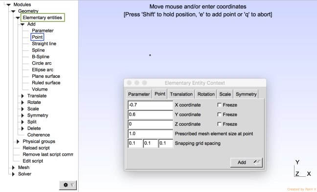
Creating points in Gmsh
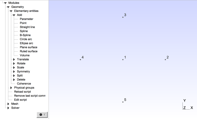
Defining five points to create a circle
To generate a circle you will need to connect the points created using the Circle arc feature in the tree, first choosing the starting point, the center of the circular arc and the end point as shown below.
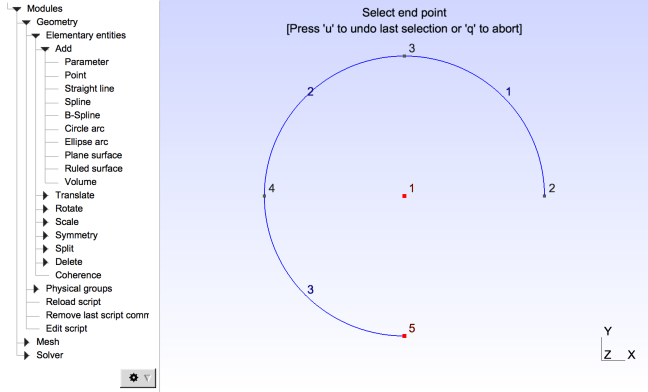
Boundaries of the circle
Note that Line 1 connects Point 2 and Point 3 with center in Point 1, Line 2 connects Point 3 and 4 with center in Point 1, and so on. Once we have connected all the dots, we have identified the circumference of the circle, hence, only its boundary line. Since the face of our geometry is flat, we can use the Plane Surface feature to define the circle.
The Plane surface feature enables you to create solid surfaces or with holes. First we need to select the surrounding boundary, and then if any, the boundaries of the holes within the surface.
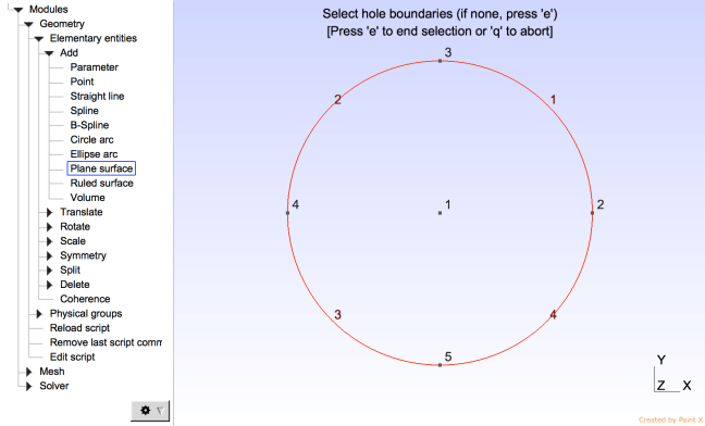
Surface of the circle
In our case we have a solid surface, so we can press ‘e’ to end the selection. This last step finalizes the creation of a circle using Gmsh’s GUI. At the end of the menu tree you will find a feature called Edit Script, when we click on it we a text editor pops up with the script that describes the geometry you have just created.

Script generated in Gmsh’s syntax
Parametrizing your geometry
For simple geometries the GUI is quite user friendly and the syntax is sequential and easy to understand, but what if we want to model and compare circles of different radii, or what if we want have more complex geometries? In this case can use a text editor to create a .dat file to generate a personalized menu on the GUI.
In the .dat file we will parametrize the location of the center of the circle and we will create an input function to read from the GUI the location in rectangular coordinates and the radius or the circle.
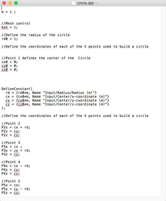
Parametrization of location of center of the circle and creation of a menu to control it along with the radius dimensions in meters
The .dat file needs to be included into our .geo file and everything should be parametrized accordingly as shown below:
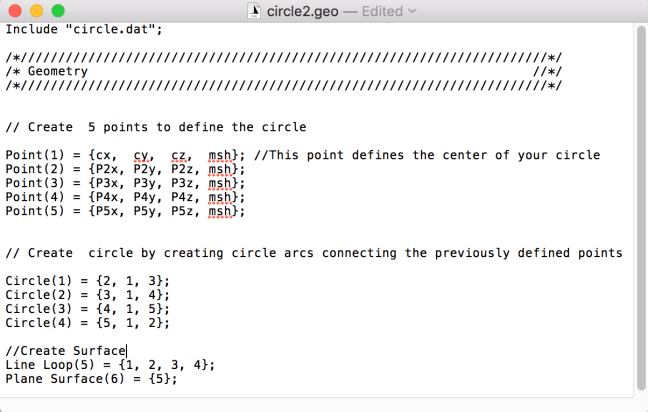
Parametrized .geo file
As we see, the coordinates are the only ones that need to be substituted with the new parameters. The numbering of the Point, Circle, Line Loop and Plane Surface features don’t need to be changed.
When we open the GUI we see the final result of our geometry: a circle that can be generated anywhere in the xy-plane, controlling the location of its center and its radius.
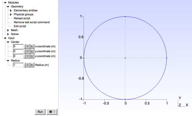
Circle generation depending on center location and radius in xy-plane
We can also take a step further and make it more general, by defining the plane where we want the circle to be created. Since we already have defined our main circle, we can clearly see that depending on the plane, we only need to move some of the points around to meet our needs.
Let’s create a new menu item using Flags. Flags are very convenient as they enable Gmsh (and GetDP) to create combinations based on choices. This addition will create a drop down box with the different plane choices:
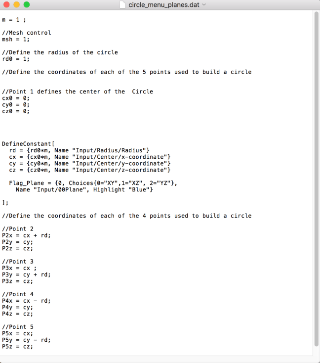
Flag_Plane Menu
As we see, the choices 0, 1 and 2, are tied to the places XY, XZ and YZ respectively.
Let’s leave the rest of our .dat file the same and just add or subtract the radius of the circle whenever needed on the .geo file.
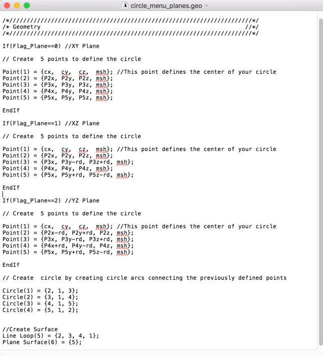
Using Flags on your .geo file
With these subtle changes we have a more general way to create circles in any of the aforementioned planes, varying the radius and position of its center.
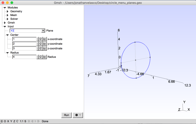
Circle in plane YZ, Center at P(1m,2m,3m) and Radius 4m

What kind of text editor do you use for typing gmesh commands, as shown above? I am new to gmesh
LikeLike
Yushen, I use Aquamacs for convenience but any text editor will do. For the blog I have used TextEdit which comes with MacOS (equivalent for Notepad on Windows).
LikeLike
would you please put the final .geo file for download?
LikeLike
Thank you Mr. Velasco. It has been very useful
LikeLike